In fact I know FA about electrics. But I'm doing an engine conversion in the Saxo I drive and the main issue so far is that the car originall ran a cooling fan setup that was controlled by the ECU, which in turn took it's signal from the two coolant sensors in the head (which controlled fuel mixture, the gauge etc etc)
Now the setup I'm fitting doesn't have this. Instead the fan is run off a standard 3 pin switch ala the BX. Three pins I'm guessing one being earth, the pther two operating the fans at varying speeds dependant on temperature?
This means the car I'm fitting that to has no wiring loom in place for such a setup, and the earlier car is all hard wired into the main loom/fuse box.
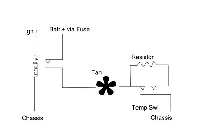
Now, having been faffing around I sat down and wondered if this simple but crude setup below would work correctly. Any ideas anyone?
I'm no electrician
- mat_fenwick
- Moderator
- Posts: 7326
- Joined: Tue Sep 20, 2005 4:08 pm
- Location: North Wales
- x 19
Re: I'm no electrician
Nope. But it would work if you replaced the earth to the relay (top left) with a 12V feed. If you want the fan to run even with the ignition off use a constant 12V, if not use an ignition switched feed. That way the current will flow to earth through the temperature switch when either the 'hot', or 'very hot' contacts are closed, closing the contacts in the relay on and allowing the fan to run.Kitch wrote:I sat down and wondered if this simple but crude setup below would work correctly.
Re: I'm no electrician
I'm not quite sure what you mean there Mat, an earth will be needed for the coil of the relay. But therin lies the problem, the relay is not drawn to show/understand the coil connections, or how the switch sets operate. As drawn can't even see what is switching the relay but presume the intention is for feeds to both fans only to be "live" when the ignition is switched on?mat_fenwick wrote:Nope. But it would work if you replaced the earth to the relay (top left) with a 12V feed.Kitch wrote:I sat down and wondered if this simple but crude setup below would work correctly.
With the engine fan, a resistor is required across 2 of the three pins of the switch for the slow and fast functions to be able to operate.
1991 BX19GTi Auto
- mat_fenwick
- Moderator
- Posts: 7326
- Joined: Tue Sep 20, 2005 4:08 pm
- Location: North Wales
- x 19
Maybe I didn't explain myself too well...assuming it is a B type relay,
(coil between 85 and 86) then if you rotate the relay 90° it should work. You need either a constant or ignition switched 12V to terminal 85 which is one side of the coil. The other side of the coil (86) is earthed via the temp. switch (when either of the contacts is closed), then allowing the main current to flow through the relay (terminals 30 & 87) to the fan.
I had actually misunderstood Kitch's original post, and thought that he wasn't bothered about fast and slow speeds - the diagram above (with my mods) will only work on fast even when the lower temperature contact only is closed in the temp. switch. (The switch works by one contact closing at (say) 85°C, the other closing as well at say 90°C)
If you're still stuck tonight mate, I'll do a simple sketch when I have a bit more time to show how the fast/slow arrangement works (with a resistor as Way2go says, or a second fan, but that gets more complex and needs more relays!)
The diagram confused me too as at first look I took it that what I now see is representative of a radiator was a centrifugal fan perhaps for internal air.mat_fenwick wrote:Maybe I didn't explain myself too well...
Basically that switch wiring needs to go in series where the connector is shown for the rad fan going to earth (not via the relay) and then when a live 30A fused feed from the battery is switched via the relay, the fan will operate on fast or slow if the resistor is fitted but fast only if the contacts are bridged as shown.
The relay coil only then only needs to be energised by an ignition switched feed so that it is on all the time that the ignition is and off when it is not.
The switch contacts of the relay route a live feed to the fan when the relay is energised (fused 30A between battery and relay switch contact).
For the Fan to operate now, the ignition has to be switched on and the temperature switch needs to be hot enough to operate.
1991 BX19GTi Auto
- mat_fenwick
- Moderator
- Posts: 7326
- Joined: Tue Sep 20, 2005 4:08 pm
- Location: North Wales
- x 19
- Vanny
- Merseyside resident
- Posts: 3582
- Joined: Tue May 17, 2005 11:48 pm
- Location: BXProject
- My Cars: BX 16v Ph2 - Jazz
BX 16v Ph2 - XPO - x 82
- Contact:
Or Mr the Kitch, if your looking for the easier option, find a late 309 or early 405 and the entire wiring loom for the fans (single or twin) is a plug and play affair, unplug from donnor, connect to sAXo, job done! I've had this setup for quite some time without a shadow of a problem, includes run on, and a connector for AC overide control!