had a crap couple of days with the meteor,
got new dizzy cap (£26.00 ffs) and rotor +plugs but it still wont start , suspect it may be the coil, turns over, fuel getting in ok but no spark at all, even tried a spark plug in the HT lead from the coil but nothing.
there is power getting to the coil.
looking at the wiring there are four wires , two green and two grey or some such colour, three wires go in the loom to the dizzy and ignition switch but one green one ends in a protected female spade connector, this is not connected to any thing,
should it be connected and if so where to.
coil wiring
-
Mickey taker
- Over 2k
- Posts: 3209
- Joined: Wed Apr 01, 2009 10:38 pm
- Location: M K
- x 1
coil wiring
1991 BX Meteor 1.6
light travels faster than sound, thats why you look intelligent and then you spoil it all by opening your mouth !!!!!
light travels faster than sound, thats why you look intelligent and then you spoil it all by opening your mouth !!!!!

My money is on the ignition module Mick.
I had one go in similar situation in a 1.6 about 15 years ago. Sometimes it ran, sometimes it dodn't. Then finally I was about 100 yds from work and it just stopped. Called the AA and he replaced the module. I didn't want to tell you this when I read the problems you were listing as I wasn't sure if you had a spark or not.
In my epxperience, no spark is more likely the module.
If you have a Haynes btw, look at the circuit diagrams for the wires in question. I'll do a scan of the relevant page in a bit for you and describe it.
-
Mickey taker
- Over 2k
- Posts: 3209
- Joined: Wed Apr 01, 2009 10:38 pm
- Location: M K
- x 1
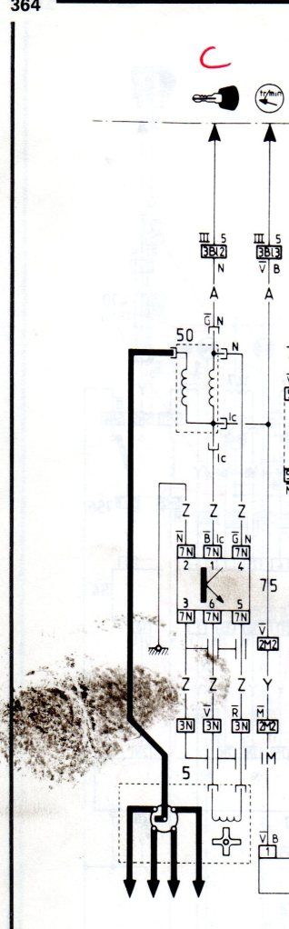
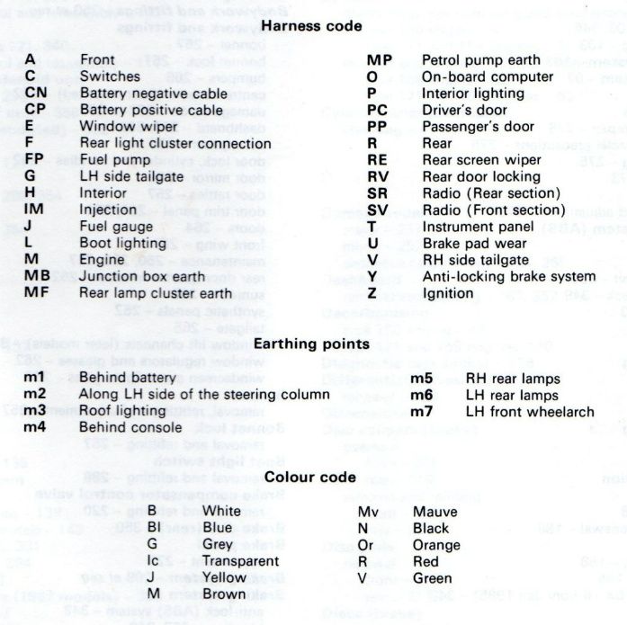
These circuit diagram are for the Mk1, but the way the system works is the same.
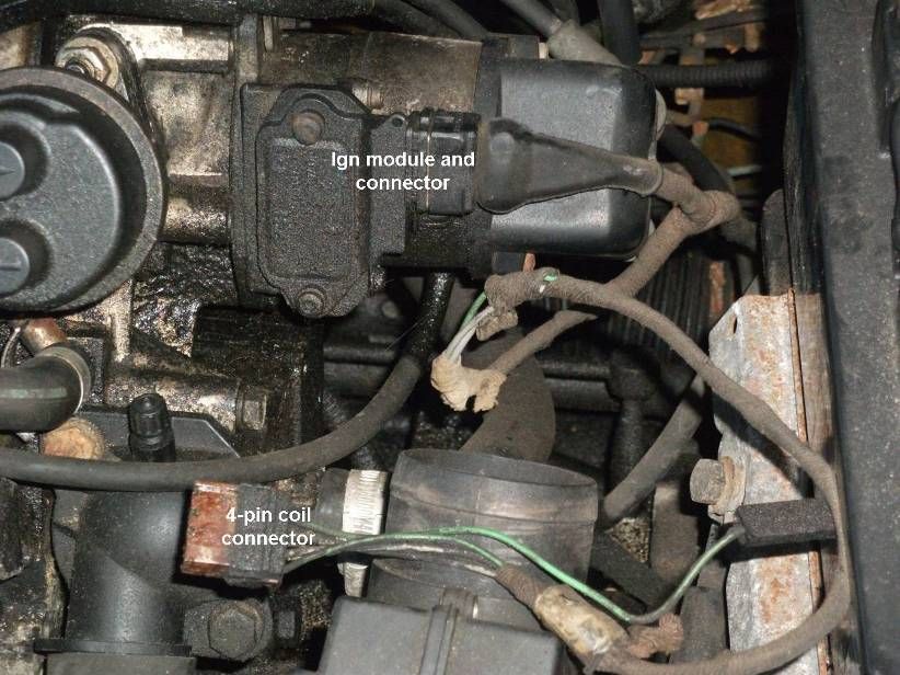
On the Mk1 the coil was conventionally fitted to the bulkhead, but on the Mk2 it looks more like a toroidal transformer and it's fitted on the front of the engine. The ignition module is on the side of the distributor.
In the diagram below, 50 is the coil and 75 is the ignition module..
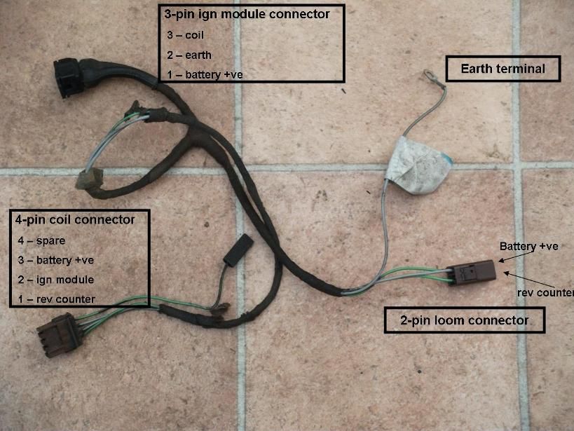
On our cars (both mk2), there is a 4-way connector plugged into the "toroidal transformer" but only 3 of the wires are in the loom (a green and 2 greys), the other green wire would be for diagnostics maybe.
I think that the difference in the wiring on the Mk2 in the diagram is the colours used, and there is no connection from pin 4 of the module to the coil (this is the module +ve feed and I think the module gets the +ve feed differently in the Mk2).
So: on the Mk2 coil, one is the +ve feed, one goes to pin 1 of the module, and one goes to the rev counter, and the other is for diagnostics (I think).
The ignition module is part of the breakerless system.
On the Mk1 the coil was conventionally fitted to the bulkhead, but on the Mk2 it looks more like a toroidal transformer and it's fitted on the front of the engine. The ignition module is on the side of the distributor.
In the diagram below, 50 is the coil and 75 is the ignition module..
On our cars (both mk2), there is a 4-way connector plugged into the "toroidal transformer" but only 3 of the wires are in the loom (a green and 2 greys), the other green wire would be for diagnostics maybe.
I think that the difference in the wiring on the Mk2 in the diagram is the colours used, and there is no connection from pin 4 of the module to the coil (this is the module +ve feed and I think the module gets the +ve feed differently in the Mk2).
So: on the Mk2 coil, one is the +ve feed, one goes to pin 1 of the module, and one goes to the rev counter, and the other is for diagnostics (I think).
The ignition module is part of the breakerless system.

According to the cct diagram, there is only one green wire which connects the magnetic pulse generator (inside the dizzy)via a plug on it' body to the external ignition module. If this was disconnected you would not get a spark BUT you need to be sure as extra wires can be present for non-installed accessories.
The important green wire connects from that body plug to pin 6 of the module.
The important green wire connects from that body plug to pin 6 of the module.
1991 BX19GTi Auto
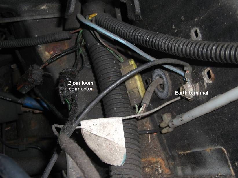
No he's talking about wires on the plug-in connection to the coil, not the module. He hasn't removed the distributor body nor the module nor the plug-in connector to the module (that connector is shrouded) so he has not seen and cannot see any of the module wires. The wires on the connector to the coil can be seen and are (left to right) green, grey, grey, green.
-
Vanny
- Merseyside resident
- Posts: 3583
- Joined: Tue May 17, 2005 11:48 pm
- Location: BXProject
- My Cars: BX 16v Ph2 - Jazz
BX 16v Ph2 - XPO - x 82
- Contact:
Might be relevant, might not, but the 16v has a loose connector which comes directly from the connector on the coil. It's purpose is for coil suppression (or in English, to stop the coil EMF being picked up on the radio), but i am yet to find any example of the valver with this wire connector to an actual suppressor.
It makes me think that this might have been either an EU requirement or a T1 supplier requirement (in the case of the valver, BOSCH might have deemed it necessary for warranty).
So it might well do nothing!
Also be aware that the wiring diagrams in the Haynes are the first technical release of the diagram, and usually nothing like what was actually fitted to the car. In the technical bulletin's that I have in front of me i could 6 different updates to the wiring diagram for the 1.6, the last being in 1991, so don't be surprised if waht you see on the car doesn't match what's in the picture!

Ah, Ok! In that case even in the cct diagram you post, a green wire can be seen tee'd off the coil (common) connection going off to the rev counter.BX Meteor wrote:No he's talking about wires on the plug-in connection to the coil, not the module. He hasn't removed the distributor body nor the module nor the plug-in connector to the module (that connector is shrouded) so he has not seen and cannot see any of the module wires. The wires on the connector to the coil can be seen and are (left to right) green, grey, grey, green.
Do you have a rev counter Mick?
1991 BX19GTi Auto
-
Mickey taker
- Over 2k
- Posts: 3209
- Joined: Wed Apr 01, 2009 10:38 pm
- Location: M K
- x 1
-
Mickey taker
- Over 2k
- Posts: 3209
- Joined: Wed Apr 01, 2009 10:38 pm
- Location: M K
- x 1
OK, here's another theory then.  The BX16 has a diagnostic socket. Connections to the LT side of the coil are made to this socket. Also present on this socket are connections to a TDC sensor which go nowhere else but this socket. Perhaps there is some Citroen Dealer gadget that can couple to the diagnostic socket & your green wire to transfer operation from the impulse generator in the Dizzy to the TDC sensor for assessing and then setting the right advance settings?
1991 BX19GTi Auto