BX breakdown
-
stuart_hedges

- 1K Away
- Posts: 1679
- Joined: Mon Oct 03, 2005 10:35 am
- Location: Surrey
The spark test is a reasonable test for the whole ignition system - ie if there is a good healthy spark then the whole system is probably OK.
I presume you don't have a spark - so the next question is 'Is the low tension supply good?'
Is there current at the ignition coil? Is the terminal leading to the module live? Is the module earthed? Does the magnet induce the current in the sensor?
What happens is that the coil has 2 windings, one (primary) with relatively few thick wires and the other (secondary) with many thin windings. If a current is passed through the primary and then interrupted - a high voltage (20,000volts+) is produced in the secondary - and this is conducted by the high tension wiring (thick leads) to the spark plugs via the distributor which directs it to the appropriate plug.
The interruption of the primary circuit used to be taken care of by the contact breaker and the capacitor, but technology has replaced this with a less unreliable electronic equivalent - the rotor and coil which look after the interruption by generating a signal and the module which processes and amplifies it before feeding it to the coil primary.
You can also check the high tension leads with your meter - they should have a resistance of not more than 20,000 ohms but 10,000 is better. The most likely one to fail is the single one from the coil to the distributor.
BE CAREFUL TO AVOID SHOCKS - ESPECIALLY FROM THE HIGH TENSION LEADS.
-
mat_fenwick

- Moderator
- Posts: 7326
- Joined: Tue Sep 20, 2005 4:08 pm
- Location: North Wales
- x 19
I have had the same symptons where it turned out the coil was internally shorting (intermittantly), which meant no spark and no rev counter.
If as it sounds yours has no spark at all continually I would check out the resistance of the primary and secondary windings with your multimeter; and if you get a reading of near zero resistance, or infinite resistance then that's where your problem lies.
From memory I think you should be looking at several thousand ohms on the secondary (HT) side of the coil and a few hundred on the primary (LT) side although a Haynes manual should detail a more precise range.
You could check that there is voltage at the coil with the ignition turned on with your multimeter. I'm not familiar with the wiring on the petrol models but you may find that you only get 7-8 volts, only seeing full voltage when cranking. If you have a ballast resistor fitted then this is normal, if not then it would suggest that there is a poor connection somewhere in the circuit.
Good luck!
I presume that the AA man verified that your coil was good, perhaps by substitution.
Also check with your voltmeter and with the ignition switched “on” that the 12V supply is present and correct on the spade connectors on top of the coil. Connect the negative probe to a suitable earth. Check if wiggling the connectors makes the voltage go intermittent.
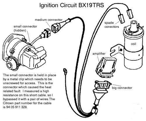
I once had a heat related problem on my 19TRS which I eventually traced to poor electrical continuity in one of the connectors in the ignition circuit.
See http://www.bxclub.co.uk/forum/viewtopic.php?t=4228 for details.
If your ignition circuit is similar to the 19TRS, you should be able to remove the ignition loom shown in the diagram together with the short cable which connects it to the sensor on the distributor body. You can then take it indoors to test it. Make a note of the correct connections to the coil. On mine they are,
RHS : one is the 12V supply from ignition key and the other is the 12V supply to the amplifier. These 2 are connected together at the spade connector
LHS : one is the switched drive to the coil from amplifier and the other is the signal to the rev counter. These 2 are connected together at the spade connector.
Put your voltmeter on the smallest resistance range typically 200 Ohms.
Short the probes together to note the short circuit resistance, which should not be above about 1 Ohm.
The idea then is to confirm that there is low resistance through the various parts of the circuit, hardly much more than the short circuit reading. Bear in mind that if the fault is intermittent then the act of disturbing the cable and connectors may temporarily make the fault go away.
There are really only 4 paths --- 2 from the sensor carrying the weak signal to the amplifier and 2 from the amplifier to the coil. One of these is the 12V supply to the Amplifier and the other is the switched drive to the coil. You should be able to find these by trial an error. You should also check "earth" connector which bolts to the chassis for good continuity.
I found the fault in the short connector between the distributor sensor and the “medium” connector, the resistance measured in one of the two wires making up the cable was up at about 9 Ohms. Waggling the cable caused this reading to vary.
Also check with your voltmeter and with the ignition switched “on” that the 12V supply is present and correct on the spade connectors on top of the coil. Connect the negative probe to a suitable earth. Check if wiggling the connectors makes the voltage go intermittent.
I once had a heat related problem on my 19TRS which I eventually traced to poor electrical continuity in one of the connectors in the ignition circuit.
See http://www.bxclub.co.uk/forum/viewtopic.php?t=4228 for details.
If your ignition circuit is similar to the 19TRS, you should be able to remove the ignition loom shown in the diagram together with the short cable which connects it to the sensor on the distributor body. You can then take it indoors to test it. Make a note of the correct connections to the coil. On mine they are,
RHS : one is the 12V supply from ignition key and the other is the 12V supply to the amplifier. These 2 are connected together at the spade connector
LHS : one is the switched drive to the coil from amplifier and the other is the signal to the rev counter. These 2 are connected together at the spade connector.
Put your voltmeter on the smallest resistance range typically 200 Ohms.
Short the probes together to note the short circuit resistance, which should not be above about 1 Ohm.
The idea then is to confirm that there is low resistance through the various parts of the circuit, hardly much more than the short circuit reading. Bear in mind that if the fault is intermittent then the act of disturbing the cable and connectors may temporarily make the fault go away.
There are really only 4 paths --- 2 from the sensor carrying the weak signal to the amplifier and 2 from the amplifier to the coil. One of these is the 12V supply to the Amplifier and the other is the switched drive to the coil. You should be able to find these by trial an error. You should also check "earth" connector which bolts to the chassis for good continuity.
I found the fault in the short connector between the distributor sensor and the “medium” connector, the resistance measured in one of the two wires making up the cable was up at about 9 Ohms. Waggling the cable caused this reading to vary.
David
BX19TRS 118K E Reg 1992-2008
BX19TRS auto abs 96k F Reg
BX19TXD 150k K Reg
BX19TRS 118K E Reg 1992-2008
BX19TRS auto abs 96k F Reg
BX19TXD 150k K Reg
-
mat_fenwick
- Moderator
- Posts: 7326
- Joined: Tue Sep 20, 2005 4:08 pm
- Location: North Wales
- x 19
-
mnde

- Meteor Man
- Posts: 1453
- Joined: Tue Oct 18, 2005 5:10 pm
- Location: Aldershot, Hants
- My Cars: 2007 Citroen Xsara Picasso 1.6 16V VTX
1982 Citroen GSA Spécial Estate - gone to a new home
1991 Citroen BX16 TGS Meteor - still out there somewhere!
This is all good stuff, thanks guys 
Ellevie: No the first guy to arrive from Westbourne recovery (sent by the AA) didn't verify the coil was good. In fact he didn't do any electrical tests whatsoever apart from the rudimentary spark test...
The difference between the ignition circuit pictured, and the set-up in my car is that mine has a small wedged shape coil mounted near the fuel filter, with a single multiplug connector instead of spade connectors, and the ignition module is bolted to the side of the distributor.
The wires from the ignition module hang perilously close to the wires from the engine temp sensor switches and the braided battery clamp earth lead, and they're partially wrapped in dirty old insulating tape. I'm not sure it's possible to dismantle this loom in the same way as the setup on your 19TRS.
There is a female spade connector on a wire sprouting from the coil multiplug that goes to nowhere. Anyone know why this wire exists? I remember finding a similar redundant wire on ren16tx's St Tropez.
Stu: Yeah I was slightly furious, considering the first guy to turn up and pronounce the car dead... was driving a flat bed truck. When he called back to base he was told by the AA that he couldn't take me away. I had to phone to upgrade to Relay and then they called out a second truck which was another 45 minutes.
Cheers,
Mark.
I wonder if the orphan connector is intended to be a diagnostic test point. Perhaps it may be possible to measure the 12V supply at this point --- it's probably just connected to one of the low tension terminals on the coil.
Could you post some pictures of the ignition circuit from various viewpoints ?
Could you post some pictures of the ignition circuit from various viewpoints ?
David
BX19TRS 118K E Reg 1992-2008
BX19TRS auto abs 96k F Reg
BX19TXD 150k K Reg
BX19TRS 118K E Reg 1992-2008
BX19TRS auto abs 96k F Reg
BX19TXD 150k K Reg
-
stuart_hedges
- 1K Away
- Posts: 1679
- Joined: Mon Oct 03, 2005 10:35 am
- Location: Surrey
I'd have been more than furious.mnde wrote:Stu: Yeah I was slightly furious, considering the first guy to turn up and pronounce the car dead... was driving a flat bed truck. When he called back to base he was told by the AA that he couldn't take me away. I had to phone to upgrade to Relay and then they called out a second truck which was another 45 minutes.
Go check out First Call - I'm on their basic thirty quid cover and I've no complaints - they've always got me and the car home.
EDIT: I wonder if you should be ringing Watchdog... or at least the consumer pages in your paper. Sounds like you shelled out a lot of money for not much cover.
First Call have some dodgy clauses though....
"21. Claims directly or indirectly caused by or contributed to or arising from ionising radiations or contamination by radioactivity from any nuclear fuel or from any nuclear waste from the burning of nuclear fuel; or the radioactive, toxic, explosive or other hazardous properties of any explosive nuclear assembly or nuclear part of it; war, invasion, terrorism, foreign enemy hostilities ( whether war is declared or not), civil war, rebellion, revolution, military force or coup; or pressure waves caused by aircraft or any other airborne devices travelling at sonic or supersonic speeds."
Last time my car was invaded by terrorists the RAC came out with a crowbar and saw them off for me. At least I got value for money! Plus you never know when you're gonna get buzzed by tom cruise and have your windows blown out. The supersonic twat.

-
DLM

- Our Trim Guru
- Posts: 1620
- Joined: Mon May 16, 2005 6:41 pm
- Location: Gosport, Hampshire, UK
- My Cars: Historically, lots of BX hatches/estates in the 90s/00s - 16/19i/17td/19d
Recent scruffy diesel n/a estate - "The Red Shed" - is no longer mine. - x 9
Seem to recall that there are (at least) 2 ignition setups for 16/19s - Bosch and Ducellier.
My feeble memory suggests your is the Ducellier (working on the colour of the dizzy cap, which might be a red herrring). I'll have a quick look in the 15/16/19 Petrol Revue Technique manual and see if that has any more info as it often has some of those little things Haynes bypasses . It might also have some indication of your spare socket (not uncommon on petrol BXs AFAIR). I've seen the module in a slightly different position on other BXs but the installation is equally messy as it's always on a goodly bed of heat-sink.
My feeble memory suggests your is the Ducellier (working on the colour of the dizzy cap, which might be a red herrring). I'll have a quick look in the 15/16/19 Petrol Revue Technique manual and see if that has any more info as it often has some of those little things Haynes bypasses . It might also have some indication of your spare socket (not uncommon on petrol BXs AFAIR). I've seen the module in a slightly different position on other BXs but the installation is equally messy as it's always on a goodly bed of heat-sink.
Back on two wheels and pedal power for the moment.
Thanks for the pics, it looks like the circuit you've got is something like this,
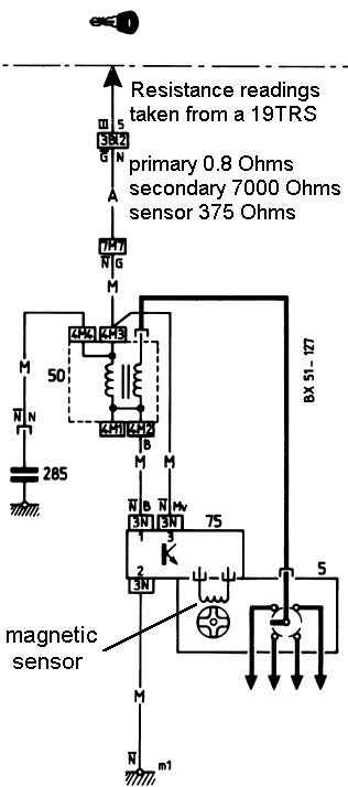
It's difficult to see from the pictures but I am guessing that in addition to the 3-way connector on the amplifier that there is a 2-way connection directly from the amplifier to the sensor in the distributor housing, just to the left of the 3-way connector. Can you confirm this ? If this is the case then it looks like there is even less to go wrong compared with my 19TRS which has two cables and 3 sockets between the sensor and the amplifier.
From the diagram, it looks like your spare connector is in fact the one shown going to the capacitor/suppressor/condenser.
You said something earlier about insulating tape on the cable. If this looks like a diy job then it's probably worth cutting this away to see if a wire is broken underneath.
You should be able to measure 12V on the 4-way connector on the coil with the ignition turned "on". It looks like you should be able to stick the meter probe down the back of the connector. The 12V should be available on all 4 contacts.
If you have not done so already, apply a squirt of WD40 or similar to the contacts in the 3-way connector at the amp and the 4-way connector on the coil and push them on and off 3 or 4 times to clean the contacts. Do the same for the connector between the amp and the sensor, if applicable.
Using the lowest resistance range you should be able to check for continuity of the two wires between the coil and amplifier connectors. Also verify that the third contact on the coil connector has good continuity to "earth". See if you can identify where this is bolted to.
The diagram shows some readings I have taken on my 19TRS. Hopefully you will be able to read something similar on the TGS. The 7000 Ohms reading was taken from the HT to LT connectors.
If the 12V supply and earth connection and cable connections check out ok, then it will be time to look at the individual components.
Good luck !
David
BX19TRS 118K E Reg 1992-2008
BX19TRS auto abs 96k F Reg
BX19TXD 150k K Reg
BX19TRS 118K E Reg 1992-2008
BX19TRS auto abs 96k F Reg
BX19TXD 150k K Reg
-
mnde
- Meteor Man
- Posts: 1453
- Joined: Tue Oct 18, 2005 5:10 pm
- Location: Aldershot, Hants
- My Cars: 2007 Citroen Xsara Picasso 1.6 16V VTX
1982 Citroen GSA Spécial Estate - gone to a new home
1991 Citroen BX16 TGS Meteor - still out there somewhere!
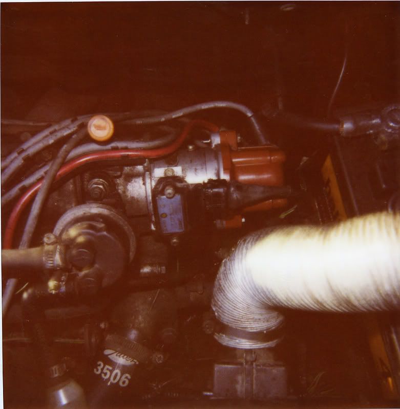
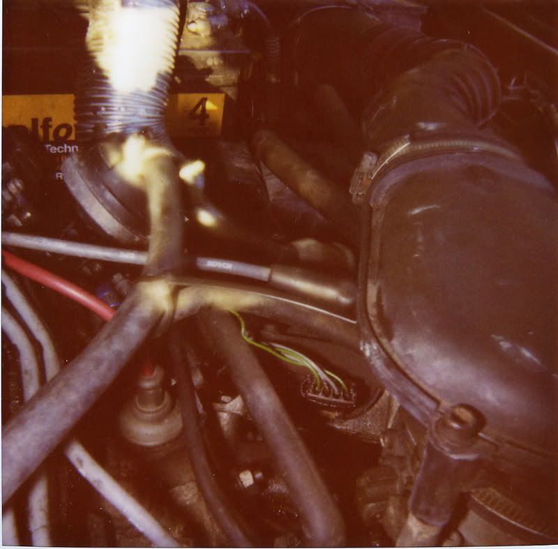
Here are some digital pics:


I'd already tried spraying the connectors with WD40 and pushing them on and off several times. There's no additional 2-way connection from the ign module to the distributor body. Mine is Ducellier ignition I think. The other Meteor has Bosch and has a black dizzy cap with small crosshead screws, instead of these gold hex headed screw/bolts. I haven't had an opportunity to get the multimeter out yet - but may do tomorrow!
Mark.