Overhauling not removal/re-fitting
Is there a sticky for this? .. If so would someone post a link?
I cannot seem to find it.
Also if there is a repair kit would anyone have the Citroen Part No.?
If a repair kit is no longer available would anyone know what the "O" ring sizes are that form the kit and what "O" ring material should be used.
Finally, does anyone have, (or know of a link for), an "exploded view" of the unit?
Thanks to all
Overhauling a steering pinion unit
-
Turboalternator
- Confirmed BX'er
- Posts: 82
- Joined: Tue Apr 28, 2009 7:22 pm
Overhauling a steering pinion unit
19 TRS Estate
In the past: 2CV, Dyane 4, GSA
Be faithful to your BX and she'll be faithful back
In the past: 2CV, Dyane 4, GSA
Be faithful to your BX and she'll be faithful back
-
RxBX
- Over 2k
- Posts: 2241
- Joined: Wed Jan 28, 2009 11:51 am
- Location: DERBYSHIRE
- x 1
Hi Turboalternator,
I hope your keeping okay ?
Take a look at THIS for the repair kit info (Hopefully it's still available) and THIS link to two further Pdf files for the exploded view/cross section to understand the removal procedure in addition to that shown/described in the first link.
I hope this may be of help to you !

RxBX
I hope your keeping okay ?
Take a look at THIS for the repair kit info (Hopefully it's still available) and THIS link to two further Pdf files for the exploded view/cross section to understand the removal procedure in addition to that shown/described in the first link.
I hope this may be of help to you !
RxBX
-
Turboalternator
- Confirmed BX'er
- Posts: 82
- Joined: Tue Apr 28, 2009 7:22 pm
Pinion Steering Overhaul
Hallo RxBx, (R.)
I'm fine thank you .. hope you are well too.
Thank you for the info. Just great and exactly what I was looking for!
Message to any moderator: If you are looking in and if this does not already exist as a sticky could RxBx's input be put in as a sticky?
To anyone else: If you know the "O" ring sizes/material please post.
All the best R. and once again thanks.
Turboalternator
19 TRS Estate
In the past: 2CV, Dyane 4, GSA
Be faithful to your BX and she'll be faithful back
In the past: 2CV, Dyane 4, GSA
Be faithful to your BX and she'll be faithful back
-
Vanny

- Merseyside resident
- Posts: 3608
- Joined: Tue May 17, 2005 11:48 pm
- Location: BXProject
- My Cars: BX 16v Ph2 - Jazz
BX 16v Ph2 - XPO - x 103
Some of the information on the Japanese site;
http://www.mars.dti.ne.jp/~ynar/bxorg_a ... /m23e.html
IS NOT CORRECT AND WILL DAMAGE YOUR CAR!!!
I found out the hard way, blew up the PAS ram, put a 4inch split down the body.
The seals shown fitted to the pinion valver are NOT correctly fitted. I believe they are wrong for both left and right hand drive!
There are numerous write ups on this forum about various methods of accessing the pinion, and i believe there is a step by step guide on the main page http://www.bxclub.co.uk possibly written by Oscar.

-
Turboalternator
- Confirmed BX'er
- Posts: 82
- Joined: Tue Apr 28, 2009 7:22 pm
Steering Pinion overhaul
Hallo Vanny,
Thank you for your post.
A little shocked and concerned to see your post, however.
Can you be a little more specific about links .. the link you have given is the BX Club home page.
On the Japanese method, I can't understand why following its overhaul procedures should have resulted in so much damage to the steering RAM since the overhaul, no matter of what method used for overhauling, was carried out with a Citroen Kit.
Also the steering ram is designed to handle the full pressure that the FDV delivers so why should it have exploded? After all the only thing that the steering pinion does, in stages, is to divert pressurised hydraulic fluid to one or the other end of the Ram.
Don't get me wrong I do believe that you did experience such catastrophic damage but what I am saying is that I do not understand why the Japanese method of overhaul should have caused it.
Perhaps you or anyone else could clarify a bit more?
Best wishes,
19 TRS Estate
In the past: 2CV, Dyane 4, GSA
Be faithful to your BX and she'll be faithful back
In the past: 2CV, Dyane 4, GSA
Be faithful to your BX and she'll be faithful back
-
mat_fenwick
- Moderator
- Posts: 7330
- Joined: Tue Sep 20, 2005 4:08 pm
- Location: North Wales
- x 22
I've copied below what was written in the DIY section, thanks to Oscar Franklin for the write up:
Get the engine bay steam-cleaned- it will make this job a lot cleaner and easier, and cleanliness is a necessity when working on the hydraulic system.
First job is release the driver's side road-wheel nuts. When the car is on axle stands, remove the wheel.
Then drop the exhaust. Put the car up on axle stands front and rear, and get as much height as possible. Make sure that it is absolutely secure - give it a good shake to see that it doesn't topple over. You may want to put jacks under the two rear side jacking points too as an extra security measure. Remember that there will be a lot of tugging and shoving - the car should be absolutely stable.
Put the suspension in "Low" and release the pressure release screw on the front of the FDV by ¼ turn with a 12 mm spanner.
At the engine end, undo the exhaust from the manifold. You'll need a 10mm socket and the longest drive you can find to do this. If you have small arms, you may be able to get close enough with a normal drive. Retain the cup washer, spring and fibre washer that are part of the fitting. Remember the order they go back on to the bolt - fibre washer, then spring, then cup washer, concave side upwards. Make sure the exhaust doesn't damage the hydraulic pipes in the vicinity when it comes down.
Once the exhaust is free of the manifold, undo the rubber hangers. There are three. Two are easy, one requires a sort of lift and turn. A bit of silicon spray will make things slightly easier.
Once the exhaust is free, take the opportunity to check it for damage, holes etc and replace any sections that need replacing.
Undo the handbrake cable from the lever on the caliper, and take off the two nuts at the end of the cable. Feed it back through the first guide.
Back under the engine. Take the handbrake cable back through the next two guides and tuck it up out of the way behind your head. This will give you more room.
Remove the heat shield, the bent piece of tin between the pinion valve and the exhaust pipe. This is held on with one 8mm nut and bolt and a spring in the shape of a coat hanger. The heat shield is not an optional extra - it will need to be replaced or your pinion valve will fail.
Working inside the car now. Remove the trim panel on the front of the steering wheel with a sharp tug, to expose the steering wheel nut. Take the nut off with a 22mm socket and retrieve the washer underneath. Remove the steering wheel by tugging upwards in a firm manner, holding both side of the wheel.
Behind where the steering wheel was, you will see two tiny torx head screws, holding the steering wheel shroud. These should be removed with a 1mm allen key or correct torx drive. Underneath the shroud, there are 4 size 20 torx screws. Remove these with the correct torx drive or a 3mm allen key. Remove the shroud and retain the pieces of trim from around the indicator and headlights stalks. You'll need to disconnect the "lights on" warning beeper and the dash lights dimmer switch.
Drop the steering wheel column by undoing the 4 13mm nuts that secure it to the bracket. Unclip the wiring connections for headlights etc. - these pull off. Leave the ignition wiring in place.
You've now got access to the steering column coupling which is undone with a 13mm socket and spanner. Disconnect the steering coupling and the steering column with a sharp tug.
Back underneath the car. Undo the allen bolt securing the hardy disk (rubber disk attached to the steering coupling) to the pinion valve with a 6mm allen key and 12mm spanner. Pull the coupling back inside the car. Examine the rubber disk for cracks by flexing it. If it is cracking, new couplings are available for about £10.
Now working on the pinion valve. With the wheels in the straight-ahead direction, scribe a datum mark showing the relative position of the pinion valve spindle and the pinion valve body. This is important, as otherwise there is a risk of refitting the valve in a position that doesn't correspond to the rack's position.
Now look underneath the steering rack, directly below the pinion valve. There is a lozenge-shaped plate secure with 2 13mm bolts. This is a tensioning device which keeps the rack in close contact with the pinion. Undo the bolts in parallel, as the spring inside is very powerful. As the bolts become loose, be ready for the plate and bolts to fly off under the pressure of the spring inside. Retain the spring and the tensioner - a black plastic hollow cylinder that is a snug fit inside the aperture. The spring fits inside this tensioner. Be aware that there is a narrow o-ring between the lozenge-shaped plate and the rack - make sure that this is retained and replaced when refitting, or LHM will leak from the plate.
Back onto the pinion valve. Undo the two pipes that feed the ram from the pinion valve with a 12mm spanner. Remember which one goes where, although it is difficult to fit them into the wrong holes.
Undo the narrow, high-pressure feed line that goes into the right-hand side of the pinion valve as you are looking at it from below. This needs either a 9mm spanner, if you have one, or a 3/8 spanner if you don't. The low pressure return is undone with a 12mm spanner. Space here is extremely limited and you will find yourself working a ¼ turn at a time. Be patient. When they are completely undone, you may need to pull them out of their holes slightly.
Once these two pipes are undone, undo the 2 cheesehead bolts that secure the pinion valve to the steering rack with a 6mm allen key.
Once these bolts are undone, the pinion valve will pull out.
Refitting is the reverse of removal, except for a few points:
- You'll need to fit new seals to the high pressure feed and low pressure return. The seals that GSF supply are about 1mm too long which makes locating the pipes in the pinion valve extremely difficult. Cut this 1mm off.
- locating the high-pressure feed and low pressure return in the pinion valve is still extremely difficult, even with truncated seals. It will be slightly easier if the pinion valve has not been bolted to the steering rack body yet. Don't tighten the pipes up - just locate them and get them started. It is even easier if you locate and start them before offering the pinion valve up to the steering rack at all. If you do this, make sure that your datum marks line up before refitting the valve.
- This job is made slightly easier again if you uncouple the two pipes from each other. They are held together in a small bracket on the front of the subframe. Removing one from the bracket will give a little more room for manoeuvre. Don't forget to recouple them subsequently.
- Don't forget to retighten the pressure release screw on the FDV!
- You can test the operation of the new pinion valve before refitting the exhaust, so long as you don't take the car for a run. The exhaust won't get hot enough to damage the seals in only a couple of minutes of operation.
- When refitting the exhaust, reprop the car as described above, making sure it is completely stable. Feed the front end of the exhaust pipe over the subframe towards the manifold before mounting the rear end on the rubber hangers. If you don't, then you won't have enough room to clear the subframe subsequently.
- The washer-spring-washer assembly can be fitted by one person using gaffer tape to hold the assembly both together, and in place on the bolt. It's easier with two people. One works from the top of the car, reaching in to the manifold from the passenger side of the engine bay, holding the 10mm head bolt, washer-spring-washer assembly and if possible 10mm nut in place with one hand. The other works from underneath the car with the longest drive they have, to offer up and tighten the nut on the bolt. Use a jack to hold the exhaust pipe in place while all this is going on, as you will find it very difficult to manipulate nuts, drives etc while holding the exhaust pipe up with one hand. The jack need only be hand-tight, not tightened with a lever.
- Don't overtighten the nuts securing the steering column to the bracket, as the bolts, which are welded in, can shear. They won't take anything like the torques used on more modern cars, even though the assembly looks similar.
- When the steering column has been refitted, there may be a knocking sound or vibration or movement in the wheel. This is often because the lower steering column bush has dropped a little. To fix it, undo the coupling and give the steering wheel a sharp tug upwards. This will drive the bush back into position.

1993 1.9 TZD Turbo Estate
1996 3.9 V8 Discovery
1993 VW LT35 campervan
1985 Hyundai Stellar V8
2016 Hyundai iLoad
-
Vanny
- Merseyside resident
- Posts: 3608
- Joined: Tue May 17, 2005 11:48 pm
- Location: BXProject
- My Cars: BX 16v Ph2 - Jazz
BX 16v Ph2 - XPO - x 103
the pinion by its nature does not divert pressure as you have put it, but release pressure from the ram. If the seals are not placed in the correct order (there are more grooves than seals, so you CAN put them in the wrong places) then in one direction the pressure in the ram will not be released.
The theory at the time (on this forum) was that there might be a hydraulic lock/air lock stopping the ram coming back, so after various attempts to free the lock (including blowing the high pressure lines to the rack) under some but not a lot of force on the steering wheel the PAS ram eventually burst. It failed along the welded seam, as a result of repeated over strain.
I would suggest you use the search function of the forum to find the somewhat extensive thread on my problem, caused by the incorrect instructions on the Japanese site.
With regard the copy of the description MatF has provided, i find 30 to 40% of the steps in the guide pointless/unnecessary (having done the job rather a few too many times now) HOWEVER it is a very explicit guide and i can't see anything obviously at fault dangerous about it.
-
Vanny
- Merseyside resident
- Posts: 3608
- Joined: Tue May 17, 2005 11:48 pm
- Location: BXProject
- My Cars: BX 16v Ph2 - Jazz
BX 16v Ph2 - XPO - x 103
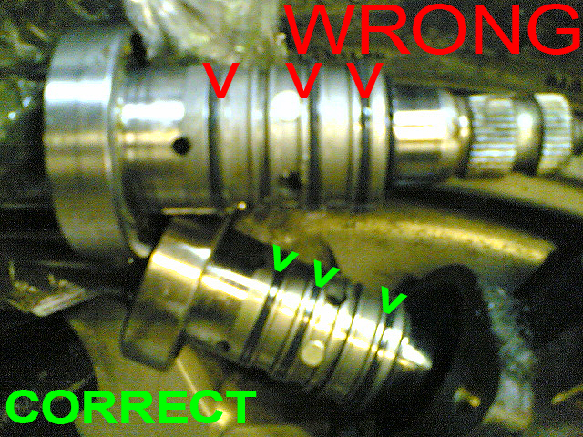
just to make this a little more obvious, below is a picture of the pinion that caused my PAS rack to fail as it is incorrectly fitted following the Japanese guide, and how it SHOULD look (this is the pinion currently fitted to my car, and the arrangement is as per the way it left the factory in france;
-
GeZ
- New Member
- Posts: 5
- Joined: Tue Mar 30, 2010 10:58 pm
Hello to everyone!!Vanny wrote:just to make this a little more obvious, below is a picture of the pinion that caused my PAS rack to fail as it is incorrectly fitted following the Japanese guide, and how it SHOULD look (this is the pinion currently fitted to my car, and the arrangement is as per the way it left the factory in france;
I would like to say that the japanese finally was not wrong as after dismantling my pinion valve I found the o-rings fitted the "wrong" way from the factory and I have photographed the markings on the valve body from the o rings which prove this. Probably there are different bodies for the same pinion valve which lead the pressure to different chambers that's why there are 4 different positions for the o rings.
-
Vanny
- Merseyside resident
- Posts: 3608
- Joined: Tue May 17, 2005 11:48 pm
- Location: BXProject
- My Cars: BX 16v Ph2 - Jazz
BX 16v Ph2 - XPO - x 103
-
GeZ
- New Member
- Posts: 5
- Joined: Tue Mar 30, 2010 10:58 pm
Yes it is LHD and here is the photo of the body with the markings

and here is the contains of the repair kit (sorry, it has three o rings not one that is in the photo). It has 6 different coloured caps (integrated with the upper cap now!!) which are dependent of the marking or the colour of the valve body(mine is brown)

and the pinion valve finished!!!!

and here is the contains of the repair kit (sorry, it has three o rings not one that is in the photo). It has 6 different coloured caps (integrated with the upper cap now!!) which are dependent of the marking or the colour of the valve body(mine is brown)
and the pinion valve finished!!!!
-
paulwitchard
- BXpert
- Posts: 134
- Joined: Fri Feb 23, 2007 10:18 am
- Location: Normandy
- x 1
That's helpful, I need to do this job, collected the parts from the local Citroen dealer yesterday (less than 24 hours from order to delivery), I did wonder what all the coloured bits were for!
Paul in Normandy - BX 1992 Millesme 1.9D, 1999 Peugeot 806 2.1 TD (the Bus) - gone bang on the M25, in a scrapyard somewhere in the SE of England, 1985 Visa Decouvrable, 1990 Land Rover 110TD (Great Uncle Bulgaria),1999 Isuzu Trooper, 1991 Hymer motorhome with Peugeot J5TD power, and a shedfull of mopeds!
-
Defender110
- Over 2k
- Posts: 5918
- Joined: Wed Dec 16, 2009 8:02 pm
- Location: Harwood, Bolton
- My Cars: Land Rover Discovery Series 1 200tdi 3 door
Land Rover Discovery Series 2 Facelift TD5
2020 Fiat Panda cross 4x4 twin air. - x 27
Very interisting stuff, I wonder what the different colour caps refer to?
Are all the caps the same or do some have different size seals installed, are some output shafts different diameter? Was this a Citroen kit or a OEM parts kit as I note the kit in the Japanese version just shows one cap, perhaps this pinnion valve is fitted to other applications other than BX cars?
The left hand drive theory for the Japanese version is doubtfull as Japanes cars are RHD so perhaps the moral here is double check the position of the original seals when dismanteling.
Kevan
1997 Mercedes C230 W202
2003 Land Rover Discovery Series 2 Facelift TD5 - Daily driver / hobby days and camping.
1993 Land Rover Discovery 200tdi Series 1 3 door - in need of TLC
2020 Fiat Panda 4x4 Cross Twin Air.
1997 Mercedes C230 W202
2003 Land Rover Discovery Series 2 Facelift TD5 - Daily driver / hobby days and camping.
1993 Land Rover Discovery 200tdi Series 1 3 door - in need of TLC
2020 Fiat Panda 4x4 Cross Twin Air.
-
macplaxton
- BXpert
- Posts: 133
- Joined: Fri Jan 08, 2010 4:47 pm
I would say that the LHD for Japan has got legs as it's a status symbol to have a foreign car as a left hooker, even if you can get a RHD. I'll ask my brother more about it when I get a chance.Defender110 wrote:The left hand drive theory for the Japanese version is doubtfull as Japanes cars are RHD so perhaps the moral here is double check the position of the original seals when dismanteling.
In the meantime, (all that) I can back this up with is the last section of this page about LHD vehicles: http://knol.google.com/k/japanese-car-auctions#
-
GeZ
- New Member
- Posts: 5
- Joined: Tue Mar 30, 2010 10:58 pm
They refer either to the colour marking (a touch of paint on the body) or to the colour of the body (for the brown, black). They are all the same so I suppose that citroen gave them just to keep the reference "alive".Defender110 wrote:Very interisting stuff, I wonder what the different colour caps refer to?
Are all the caps the same or do some have different size seals installed, are some output shafts different diameter? Was this a Citroen kit or a OEM parts kit as I note the kit in the Japanese version just shows one cap, perhaps this pinnion valve is fitted to other applications other than BX cars?
The left hand drive theory for the Japanese version is doubtfull as Japanes cars are RHD so perhaps the moral here is double check the position of the original seals when dismanteling.
this is a genuine citroen kit with code 4048 Q8.