Here you go

A simple circuit that doesn't need any extra dash switches - it uses 2 functions you wouldn't normally use together to provide wig-wag.
The only modifications are around the headlamp area.
Operating 'emergency flashers' and 'main beam headlamps' together will provide wig-wag running at the rate of the emergency
flashers (and emergency flashers will be running as well).
Emergency flashers and main beam work as normal when operated individually.
 Circuit description.
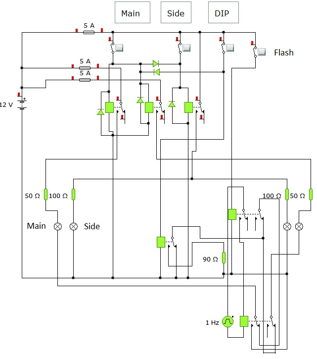
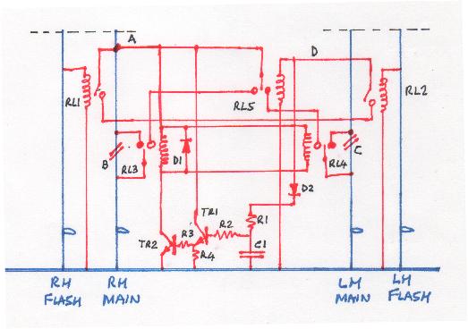
Blue lines are the original wiring and the red is the mod - note the wire cuts at B and C. All cap letters are notes refered to in this text.
Relays are drawn with the normally connected NC contact as a filled-in dot, and the normally open NO contact as a clear circle.
Power for the circuit is derived from either main beam headlamp feed - A - and if main beam only is switched on power goes to both filaments via the NC contacts of RL3 and RL4 which bridge the wire cuts B and C.
When indicators operate RL1 and RL2 operates as well but when BOTH operate together as in emergency flash power in the form of pulses appear at D.
Pulses from D charge the capacitor C1 through D2, R1.
Current through R2 is amplified by TR1 which feeds current through R3 to TR2 which turns on and operates RL3 and RL4 thus disconnecting the main beam filaments from their normal feed.
The pulses at D also operate RL5 which supplies power from A to the NO contacts of RL3 and RL4 alternately.
RL3, RL4, RL5 must be 5 pin 'changeover' relays but RL1 and RL2 can be 4 pin.
D1 is the catching diode for relays 3 and 4 - only one diode for both relays needed but it is essential - 1N4007 etc.
The electronics not breadboarded but ball-park values from some 50 years of dabbling...
R1 - 100 ohms
C1 - 150 microfarads at least 16v
R2 - 10k
TR1 - 2N2222 - any signal NPN
R3 - 220 ohms
R4 - 100K
TR2 - any 2 amp or more NPN transistor with a gain greater than 10.
If you build this and the above values don't work then I'll breadboard it for you.